Introduction to the Function of a Porous Plant Concrete Permeability Tester
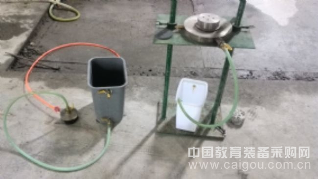
The self-made equipment used in this experiment is a porous phytosanitary water permeability tester. It consists of a fixing device, a testing device, a water supply system, and a drainage system. The test piece used is a cylindrical sample of porous planted concrete.
The fixing device includes two vertical columns and a bottom plate connected at the bottom of the columns. Between the two columns, there are upper and lower sliding platforms that can move vertically along the column axis. This allows for adjustable positioning during testing.
The testing device features a test piece sleeve designed to hold the sample. The sleeve is folded from the inner to the outer wall on both ends, with a rubber sleeve placed around the outer surface. A top cover is mounted on the test piece sleeve, and a base is installed below it. The top cap has an inlet and an outlet, with the outlet connected to the test piece sleeve. The base consists of an upper and lower cylinder, with the upper part having multiple permeable holes aligned axially, allowing water to flow into the lower cylinder. A drain pipe with a second shut-off valve is connected to the side wall of the lower cylinder, which leads to the drainage container. The lower cylinder is placed on the lower sliding platform.
The water supply system includes a transparent acrylic water container with an overflow port. A water supply pipe, equipped with a first shut-off valve, is connected to the bottom of the container and leads to the top cap's inlet. The water container is placed on the upper sliding platform.
The drainage system comprises a drainage container with an overflow opening, connected to the drain pipe on the side of the lower cylinder.
A scale is fixed to the base plate for measuring liquid levels.
The design of the device is simple, cost-effective, and easy to manufacture. During testing, the sample is placed inside the test piece sleeve and covered with a rubber sleeve. The rubber sleeve is slightly smaller than the sample to ensure a tight seal between the sample and the sleeve. It is then folded over the outer surface of the sleeve. Rubber sleeves are also placed on the upper cylinder of the top cap and the base, with rubber bands securing them to maintain airtightness. This prevents lateral leakage and ensures accurate measurements. The installation and sealing process is convenient and efficient.
The water supply device fills the system from the top down, allowing water to pass through the sample and exit via the base. The base is connected to the drainage container, and the water supply container and base are positioned on the upper and lower sliding platforms, respectively. These can be adjusted vertically to control the pressure difference, ensuring sufficient hydraulic head for accurate permeability testing. A millimeter-scale ruler on the side of the column allows direct reading of the water level difference between the supply and drainage containers.
Preferably, the top cap has a diameter of 100 mm and a height of 30 mm, while the test piece sleeve has a diameter of 105 mm and a height of 70 mm, made from PVC. The upper cylinder of the base has a diameter of 100 mm and a height of 25 mm, while the lower cylinder has a diameter of 250 mm and a height of 25 mm. These dimensions ensure a balanced weight and ease of handling during testing.
It is recommended that the water supply and drainage pipes have an inner diameter greater than 10 mm to reduce pressure loss and improve pressure transmission efficiency.
The cross-sections of the test piece sleeve, top cap, and base are all circular. The cross-sectional dimensions of the top cap and base are the same, and the test piece sleeve is slightly larger than the test piece. The base is composed of two cylinders, one smaller and one larger, to optimize drainage and sealing. This design enhances stability and measurement accuracy.
The test piece sleeve is connected to the water supply container, drainage container, base, and top cap using a detachable structure, making assembly and disassembly more convenient.
The specific steps for determining the permeability coefficient using this device are as follows:
1. Preparation: Check all components to ensure airtight connections and proper functioning of the system.
2. Fill the water supply and drainage containers to a constant level, maintaining a stable water head by closing the first and second shut-off valves.
3. Place the rubber sleeve (a round sleeve) inside the test piece sleeve, insert the test piece, and pull the sleeve over the sample to fully cover it. Position the rubber sleeves at both ends of the test piece onto the upper cylinder of the top cap and the base, then secure them with rubber bands to ensure a tight seal. Bubbles can be removed using a brush during the test.
4. Open the first and second shut-off valves, continuously fill the water supply container, and maintain a constant water level. After some time, the drainage container’s overflow will stabilize.
5. Once the water flow stabilizes, measure the amount of water collected in a beaker within a specified time period, and use an electronic balance to weigh the collected water.
6. Record the water temperature during the test.
7. Repeat the measurement steps, record the data, and calculate the average value.
8. After completing the test, remove the sample in reverse order and replace it with a new one for the next test.
Title: Porous Plant Concrete Permeability Tester
Developed by: Ningbo University of Science and Technology, Zhejiang University
In Cabinet Waste Bins,Wall Mounted Compost Bin,Plastic In Cabinet Trash Bin,In Cabinet Trash And Recycling
ZHEJIANG ERHUI TECHNOLOGY CO.,LTD , https://www.jahhome.com